Continuous Flow Ultrasonic Processing: Keep the Two Circuits Separate
A short guide to recirculating ultrasonic treatment: one circuit handles the material; a separate jacket circuit removes heat.
Ultrasonic process planning
A continuous flow ultrasonic system is not specified by watts alone. The useful starting point is the liquid, the tank working volume and the result the team needs to measure.
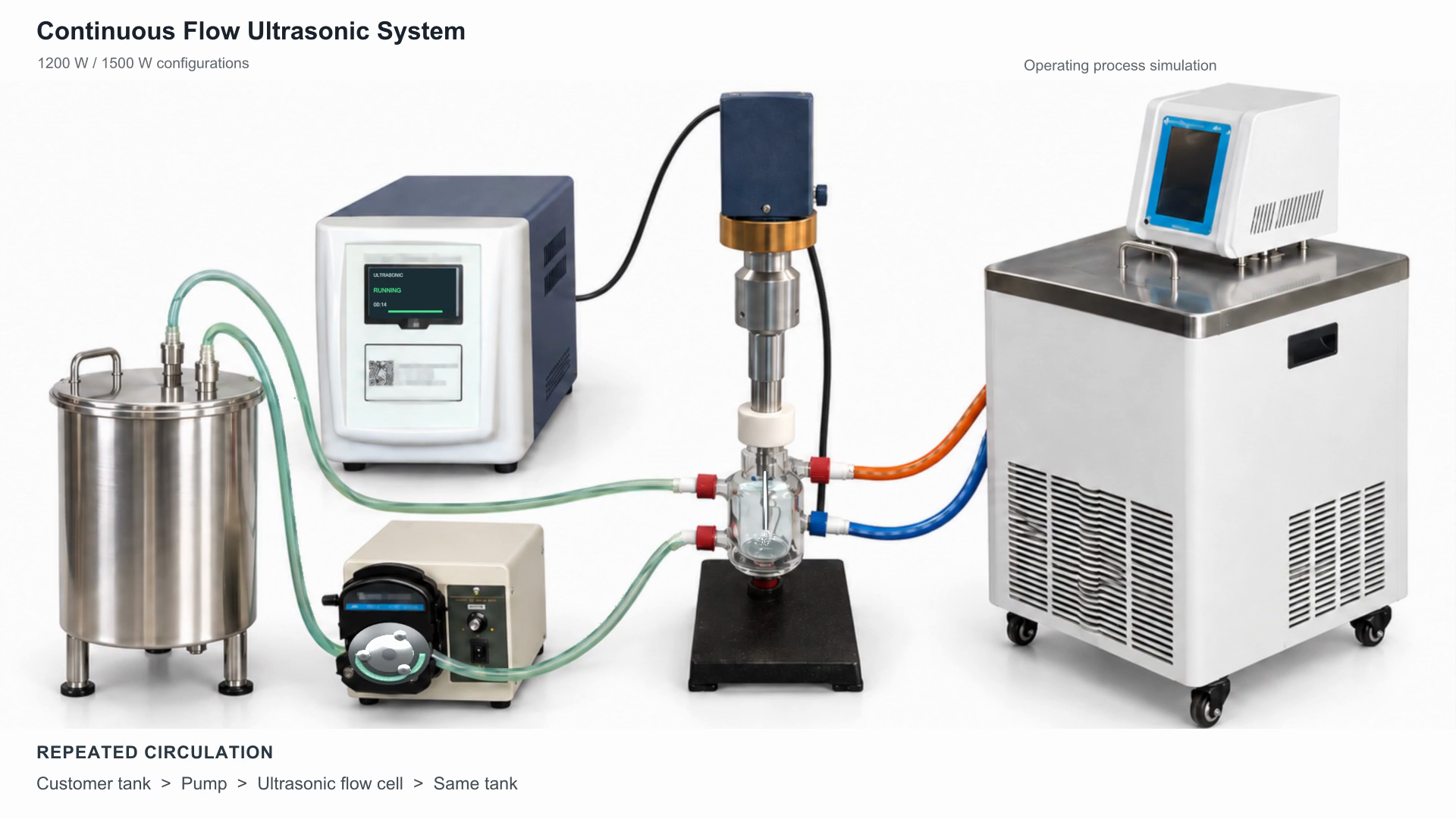
In the SJ recirculating arrangement, a peristaltic pump moves material from a customer-supplied tank into a jacketed flow cell. The immersed probe treats liquid in the inner chamber, and the outlet returns it to the same tank. Repeated circulation allows further exposure; one nominal tank turnover does not mean every portion has received identical treatment.
Cooling has a different route. A refrigerated circulator sends coolant through the outer jacket, entering low and returning high. Coolant does not mix with the process liquid. Select the cooler at the intended supply temperature and monitor the material itself, not only the bath display.
The documented SJIA-1200W and SJIA-1200E bases offer 12–1200 W adjustment and different touchscreen sizes. A 1500 W configuration is proposed but still requires engineering confirmation. Neither a base-unit batch-volume figure nor a pump flow rate is a guaranteed process throughput.
The 20-second operating process simulation shows the two circuits and repeated circulation. It is not experimental footage. For selection, send liquid properties, working volume, temperature limit, cleaning needs and an acceptance target.
Full specifications and configuration options · Watch the 20-second operating process simulation