Design Case: A Three-Glove Preparation Isolator for Creator 1S Max
A compact lyophilizer needs more than a cover around its door. This Rev. G concept adds a two-hand preparation bench, a transfer hatch and side access to the Creator 1S Max.
Design case / engineering concept
Watch the design concept
Two gloves serve the preparation bench; one is positioned near the lyophilizer. The dryer sits on the right, with its chamber door facing left through the enclosure wall.
15-second silent 3D concept, not equipment footage, CFD or a performance test. Engineering review and representative containment testing remain required. OEB5 and aseptic performance are not demonstrated.
Video details & visual descriptionOfficial video posts
The work starts before the dryer door
The design brief combines liquid mixing, manual vial filling and transfer to a 0.12 m² research lyophilizer. Putting all the gloves close to the chamber would leave too little usable preparation space. Rev. G instead puts two gloves across a left-side bench and one at the right-hand dryer interface. This is a customer-driven engineering concept, not a delivered isolator or a documented production result.
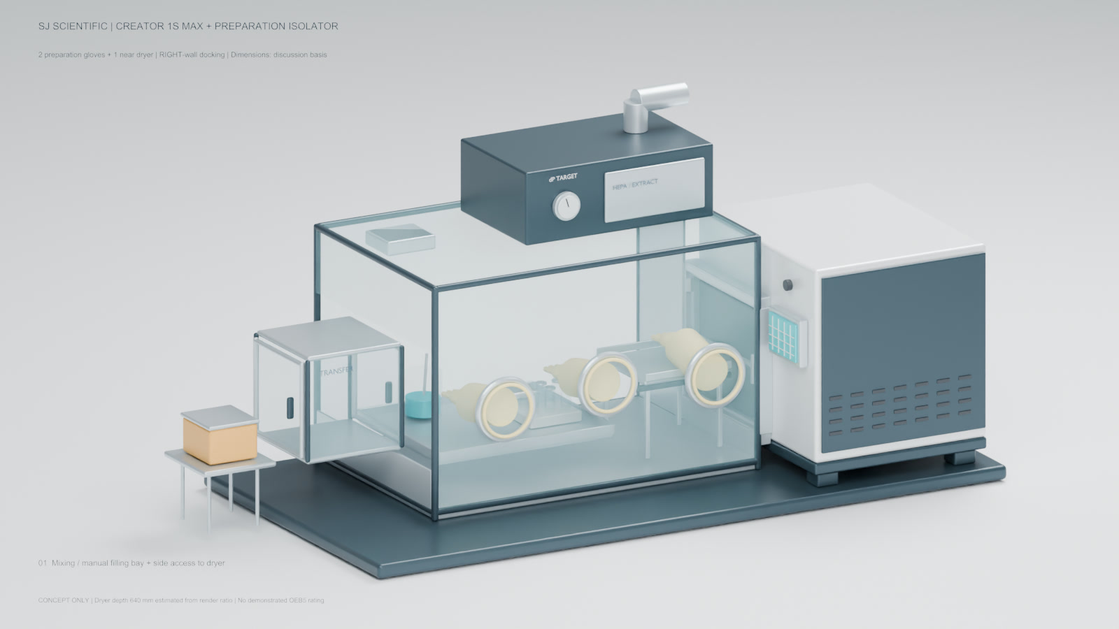
Two gloves for preparation, one near the chamber
From the operator position, the enclosure is on the left and the Creator 1S Max is on the right. The chamber door faces left into the enclosure right wall, at 90 degrees to the glove face. The HMI/control bay stays outside the enclosure. The cooled shelf is fixed; a removable vial carrier and support can be assessed without describing the cooled shelf as a pull-out shelf.
The right-hand glove is a proposed access point, not proof of one-handed loading or latching. A representative carrier, filled vials, glove length, door sweep and latch force must be tried together. Support during transfer may be necessary.
The lyophilizer basis is separate from the enclosure design
The current English Creator 1S Max specification table gives one 300 x 400 mm shelf (0.12 m²), shelf control from -50 to +60°C, minimum shelf temperature ≤-60°C and condenser temperature ≤-85°C. These are product reference values, not results measured in this proposed enclosure. Standard 1S and Max are different configurations.
The design-input front width and height below are drawing-specific. The approximately 640 mm depth is estimated from an earlier render, not measured. They do not replace the general 1020 x 810 x 790 mm product-listing envelope plus external pump. Final integration requires the approved drawing for the actual ordered unit.
Rev. G dimensions and their status
| Item | Dimension / target | Status |
|---|---|---|
| Dryer front width / height | 800 / 750.10 mm | Drawing-supplied |
| Dryer depth | Approx. 640 mm | Render-ratio estimate, not measured |
| Enclosure W x D x H | 1200 x 800 x 800 mm | Proposed; width along glove face |
| Clear preparation area | 600 x 450 mm | Proposed target |
| Removable spill tray | Approx. 650 x 550 mm | Proposed 304 stainless steel; compatibility review required |
| Glove ports | 3 x nominal diameter 200 mm | Proposed |
| Glove centres from left wall | 250 / 630 / 1030 mm | Proposed |
| Glove centre heights from base | 350 / 380 / 350 mm | Proposed; reach trial required |
| Transfer hatch outer / usable target | 350 x 350 x 350 / 300 x 300 x 300 mm | Proposed; two-door interlock |
| Adapter axial allowance | 50 mm | Proposed |
| Reserved interface region | 500 x 410 mm | Provisional; not a released opening or seal; bottom height B unknown |
| Top filter module | 700 x 450 x 250 mm | Proposed |
| Equipment envelope W x D x H | 2240 x 1100 x 1050 mm | Proposed; excludes stand, exhaust stub, staging table and service clearances |
| Common support footprint / height | 2340 x 1200 / 700 mm | Proposed option |
| Total height with support / exhaust stub | 1750 / approx. 1900 mm | Proposed |
| Enclosure differential pressure | -10 to -30 Pa relative to room | Preliminary adjustable target, not a containment acceptance criterion |
| Filter selection | H13; H14 option for assessment | Proposed; system sizing and integrity testing required |
The proposed enclosure gross envelope is 0.768 m³; free-air volume is not established. The extra 300 mm combined depth allows for the control bay outside the glove plane. Interface marks of 400 and 410 mm have different meanings; do not release a seal or clear opening from this table.
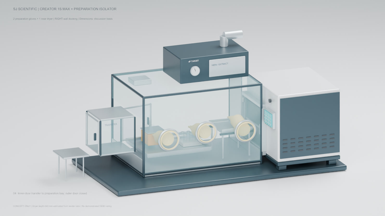
A workflow to test, not a released operating procedure
- Inspect the assembled system and establish the approved containment conditions before material handling.
- Transfer closed materials through the two-door interlocked hatch; review the transfer and cleaning method for the material.
- Use the left and centre gloves for mixing and manual filling above the removable spill tray. Rendered tools are illustrative, not a supplied automatic dosing line.
- Support and position the carrier for lateral loading onto the fixed cooled shelf. Confirm closure and latch access with representative vials.
- Run a formulation-specific freeze-drying cycle. Review chamber vacuum, backfill, pump exhaust, condenser defrost and drains as separate interfaces.
- Unload and close containers under the required containment conditions, transfer out, then clean and release the system under an approved procedure.
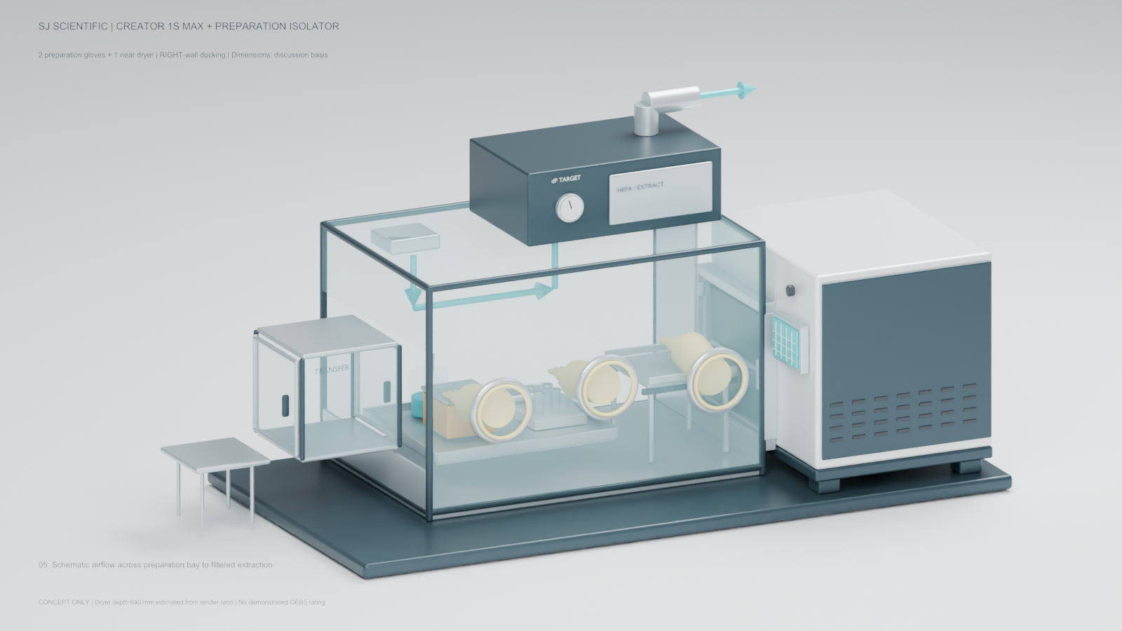
Enclosure pressure is not dryer vacuum
The preliminary -10 to -30 Pa target is a room-relative enclosure pressure difference. It is not the lyophilizer chamber vacuum setting and does not establish an OEB5 performance level. Proposed H13 filtration, with H14 considered as an option, requires system design and integrity testing. Airflow arrows in the animation are schematic, not CFD or a measured airflow study.
Containment must cover the whole task, including transfer, spills, filter changes, exhaust and cleaning. A larger enclosure requires fresh fan/filter sizing, airflow and recovery checks; an earlier smaller-box purge time cannot simply be reused. Particulate filtration does not solve solvent-vapor hazards. Flammable solvent service and aseptic filling are not established by this concept.
What needs to be agreed before manufacture
Provide the material identity and SDS, occupational exposure target, liquid volumes, vessel and vial drawings, fill volume, preparation tools, cleaning chemicals and site utilities. Engineering review then needs to close interface height B, seals, door clearances, glove reach, load support, electrical and exhaust boundaries, maintenance access and the containment test protocol. Sterile product protection, if required, needs its own design and qualification scope.
This example shows SJ's project-development approach: adapt the workspace around the actual task, expose unresolved interfaces early and agree acceptance evidence before freezing the configuration. It does not turn a custom concept into a standard certified product.
Public references and next steps
Frequently asked questions
Is this an installed or OEB5-qualified isolator?
No. This is a three-glove design concept. The video does not establish delivery, commissioning, exposure performance or OEB5 qualification. The material risk assessment and representative containment testing determine the required evidence.
Can this arrangement be used for peptide preparation?
It is a design starting point for R&D preparation and manual vial handling. Suitability depends on the specific peptide, formulation, exposure limits, solvents and product-protection requirements, not the peptide label alone.
Is the cooled shelf removable?
No. The cooled shelf is fixed in this concept. A removable vial carrier or external support is an option to evaluate; its interface and loading method still need review.
Does a 450-vial reference mean 450 vials can be handled here?
No. The published Creator reference of up to 450 positions assumes 16 mm vial outside diameter. A supported carrier, gloves, edge clearance, fill volume and condenser load may reduce the usable batch. The integrated workflow has not been demonstrated.
Does negative pressure provide sterile filling?
Not by itself. Operator containment and aseptic product protection are distinct requirements. Sterile filling needs a separately specified contamination-control and qualification scope.
Which dimensions can be used for a purchase order?
Only approved project drawings. The table marks product basis, drawing inputs, estimates and proposals separately. Interface height B, seals, service clearances and several handling details remain open.