SJ Recirculating Continuous Flow Ultrasonic System
Ultrasonic Systems
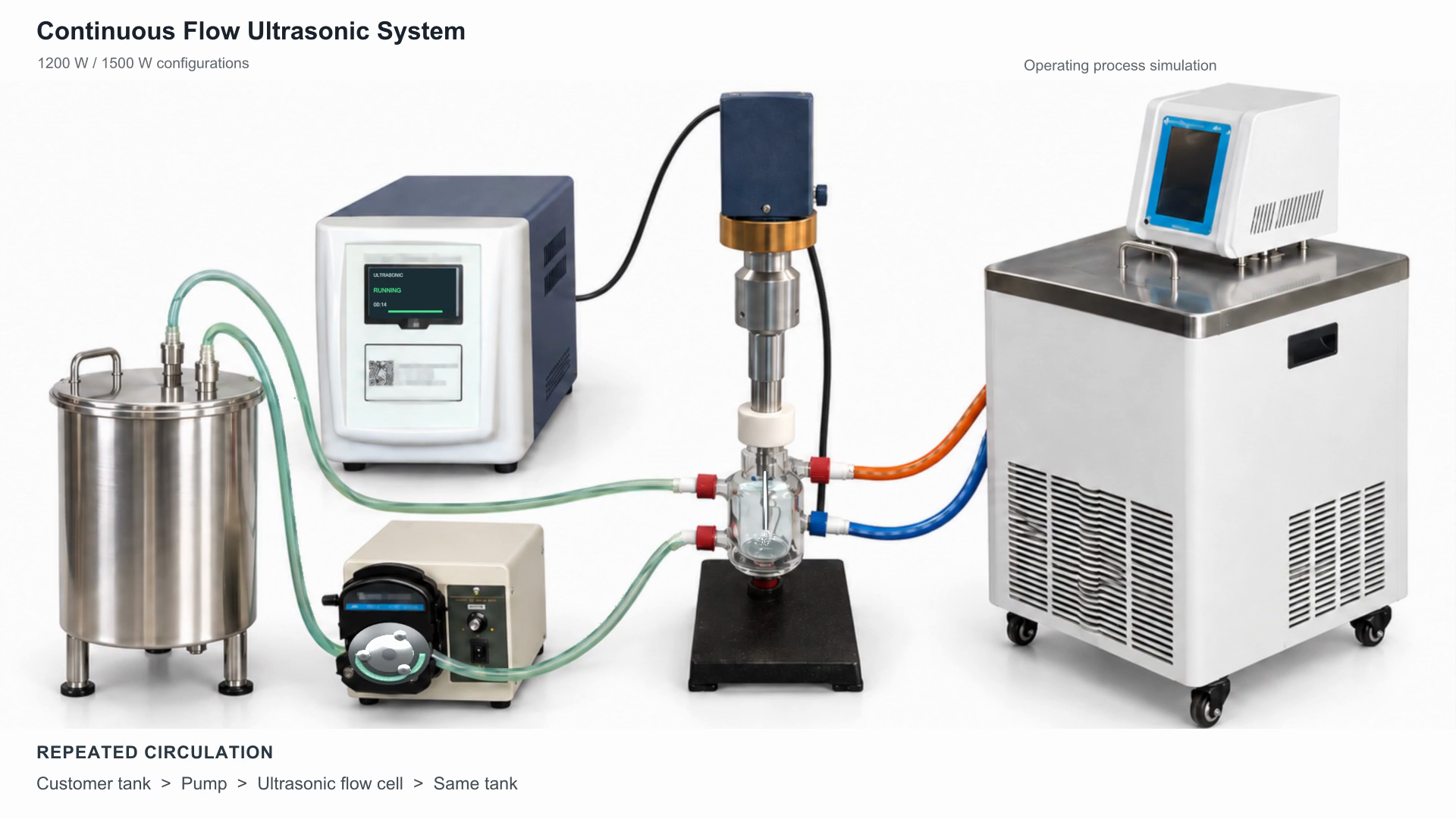
The main image and video are an operating process simulation based on equipment reference photographs, not an experiment or a measured cavitation model. The 1500 W label identifies a proposed configuration; its final specifications remain to be confirmed.
Watch the 20-second operating process simulation
Recirculating liquid treatment with independent cooling
The SJ continuous flow ultrasonic system combines a generator, matched transducer and probe, and a double-wall glass flow cell on a support stand. A peristaltic pump sends liquid from a customer-supplied tank through the probe treatment chamber and back to that same tank. Repeated circulation lets the team adjust exposure while monitoring the liquid. This is a recirculating arrangement, not a claim that one pass completes the process.
Two circuits, two different jobs
- Process liquid: customer tank → peristaltic pump → inner chamber of the ultrasonic flow cell → return to the same tank. The probe tip operates immersed in the process liquid.
- Cooling liquid: recirculating chiller or refrigerated bath → lower jacket inlet → outer jacket → upper jacket outlet → return to the cooling unit. Coolant and process liquid remain separated.
- The generator connects electrically to the transducer. Pipe connections and port positions must follow the approved flow-cell drawing; they cannot be identified solely from a reference photograph.
What is included in the system proposal?
- Core assembly: ultrasonic generator, matched transducer/probe, double-wall jacketed glass flow cell and stand.
- Configured separately: pump, pump head, tubing, refrigerated circulation unit, connectors, temperature sensing and any required interlocks.
- Customer-supplied: storage tank. Confirm tank connections, ventilation, mixing and cleaning requirements with the system layout.
- Confirm the complete supply list in the quotation. The pump and chiller shown are not automatically included in every configuration.
1200 W base-unit specifications
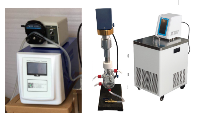
The following data belongs to two documented base units, not to a completed 1500 W flow system. Public SJ product naming is used here; the source model designations are SJIA-1200W and SJIA-1200E.
| Parameter | SJ-1200W / SJIA-1200W | SJ-1200E / SJIA-1200E |
|---|---|---|
| Adjustable power setting | 12–1200 W | 12–1200 W |
| Frequency range | 19.5–20.5 kHz | 19.5–20.5 kHz |
| Touchscreen | 4.3 inch | 7 inch |
| Pulse on time | 0.1–99.9 s | 0.1–99.9 s |
| Pulse off time | 0.1–99.9 s | 0.1–99.9 s |
| Total time including pauses | 1 s–99 h 59 min 59 s | 1 s–99 h 59 min 59 s |
| Stored settings | 20 | 20 |
| Protection alarms | Overload, no-load, overtemperature | Overload, no-load, overtemperature |
| Standard base-unit probe diameter | 20 mm | 20 mm |
| Supply voltage | 220 V; 110 V option (specify with order) | 220 V; 110 V option (specify with order) |
| Supply frequency | 50/60 Hz | 50/60 Hz |
| Generator dimensions, D × W × H | 410 × 225 × 290 mm | 410 × 225 × 290 mm |
| Generator net weight | 15 kg | 15 kg |
Source: SJ ultrasonic processor specifications and accessories table, 2022, 4.3-inch touchscreen and 7-inch E-series sheets. The 20 mm probe is the standard base-unit probe; the flow-cell probe is matched separately. Confirm voltage when ordering. Dimensions and weight describe the generator only. A power setting is not a measured acoustic-power delivery to the liquid. The source batch-volume range is deliberately not presented as flow throughput.
1200 W or 1500 W: choose the configuration, not just the number
For the 1200 W route, select the documented 4.3-inch SJIA-1200W or 7-inch SJIA-1200E base and match its probe to the flow cell. A 1500 W class system is a proposed alternative: generator model, frequency, probe, controls, flow cell and cooling requirements need engineering confirmation. The 1200 W table must not be treated as a 1500 W specification sheet.
What applications should be discussed?
Potential evaluation work includes liquid dispersion, emulsification, homogenization, extraction and cell-disruption trials. Start with the material and the required result, such as a dispersion target or extraction endpoint. Viscosity, solids, foaming, solvent compatibility, temperature sensitivity, probe wear and cleaning needs may change the suitable configuration. No universal particle size, yield, disruption rate or processing time is promised.
How to size the pump, flow cell and cooling unit
- Provide the liquid composition, viscosity, solids and particle range, tank working volume, target temperature and measurable processing endpoint.
- Specify flow-cell volume, wetted materials, seals, tubing and permitted pressure for the actual application. No glass-cell pressure rating is inferred from another manufacturer’s metal reactor.
- Select refrigeration capacity at the required coolant temperature, not only at room-temperature test conditions. Jacket heat-transfer capacity and pump pressure must also be checked.
- Monitor the actual process-liquid temperature; the cooling-bath display is not a substitute. Confirm probe immersion, flow and cooling before ultrasound is enabled.
- Record circulation flow, ultrasound settings, treatment time and sample results. Nominal tank turnover does not prove that every portion has received identical exposure.
Questions before specifying a continuous flow sonicator
Does 1200 W determine the number of litres per hour?
No. Generator rating alone cannot establish throughput. Liquid properties, treatment target, effective exposure, flow-cell geometry and cooling determine the result; representative material trials are needed.
Is this single-pass or recirculating ultrasonic processing?
The described system returns treated liquid to the same tank for repeated circulation. A once-through arrangement requires a separate engineering review and performance target.
Does the cooling water mix with the product?
No. Process liquid occupies the inner chamber and coolant passes through the separate outer jacket. The two circuits need independently confirmed connections, seals and operating limits.
Are the pump, chiller and tank standard supply?
The generator, transducer/probe, flow cell and stand form the core proposal. Pump and cooling equipment are configured separately; the tank is customer-supplied. The signed supply list defines what is included.
What should I send for a quotation?
Send material details, tank working volume, desired result, target temperature, power supply and cleaning requirements. Ask for the matched probe/flow-cell drawing, pump/tubing selection, cooling basis, test plan and support scope.
Discuss your material and required result
SJ can review the generator, probe, flow cell, pumping and thermal-control interfaces as one configuration. Agree the material trial, acceptance criteria, documentation and service responsibilities before placing an order.
Request an ultrasonic system configuration
Read the short two-circuit guide · Watch the 20-second operating process simulation